


Installing External Antennas to the T-Mobile 5G Internet Gateway
Before getting started, it’s recommended to run a few indoor speed tests using a device connected to your Gateway’s Wi-Fi. While results may vary slightly, these tests establish the baseline performance you’re aiming to improve.
Once your baseline internet speeds are measured, you can proceed with installing external antennas. Although the T-Mobile 5G Internet Gateway does not include external antenna ports, you can access the internal ports and install adapters that enable antenna connections.
In the next section of this guide, we’ll walk you through how to open the Gateway, connect the external antenna adapters, and reassemble the device.
Before you get started, you will need the following:
- A small phillips head screwdriver
- A Torx T10 screwdriver
- A small/thin flat-head screwdriver
- A thin plastic prying tool, needle-nose pliers, or tweezers
- Two or four U.FL to SMA-Female pigtail adapters (included in our 4×4 External Antenna kits)
- Tape for securing and labeling cables. Painters or Electrical tape works best.
- A secure container to keep screws and small parts safe while you work
Step-by-Step Guide to Installing Adapters for External Antennas
Step 1: Power off the T-Mobile 5G Internet Gateway and unplug the power cable.
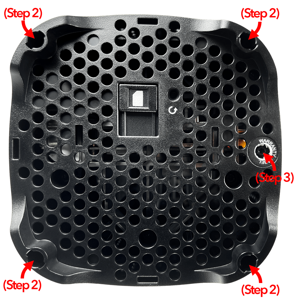
Step 2: Using a pliers, remove all four rubber feet from the bottom of the device to obtain access to each T10 screw underneath.
Step 3: Break the warranty seal to obtain access to the T10 screw underneath.
Step 4: Remove the four T10 screws revealed in Step 2 and the fifth T10 screw revealed revealed in Step 3, as shown below:
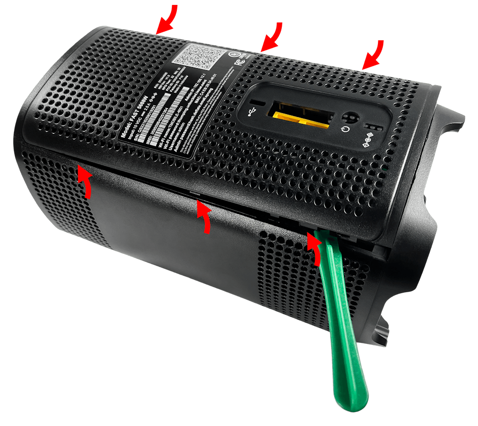
Step 5: Use the flat head screwdriver or prying tool to pry the back plate from the outer cover of the device.
Tip: There is a clasp every third of the way up on each side of the back plate, for a total of six clasps.
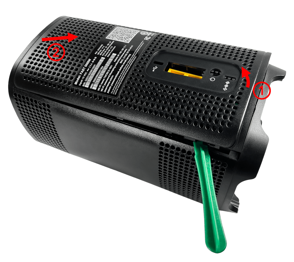
Step 6: Once the right and left sides of the back plate are unclasped from the outer cover of the device, lift up the bottom side of the back plate (1) and pull it down towards the bottom cover of the device (2), as shown below. Doing so should fully free the back place from the outer cover.
Step 7: Use a prying tool to unclasp the outer cover from the bottom of the device and then remove it from the inner enclosure by lifting it away from the bottom of the device.
Tip: There is a clasp in the center of each side of the outer cover, for a total of three clasps.
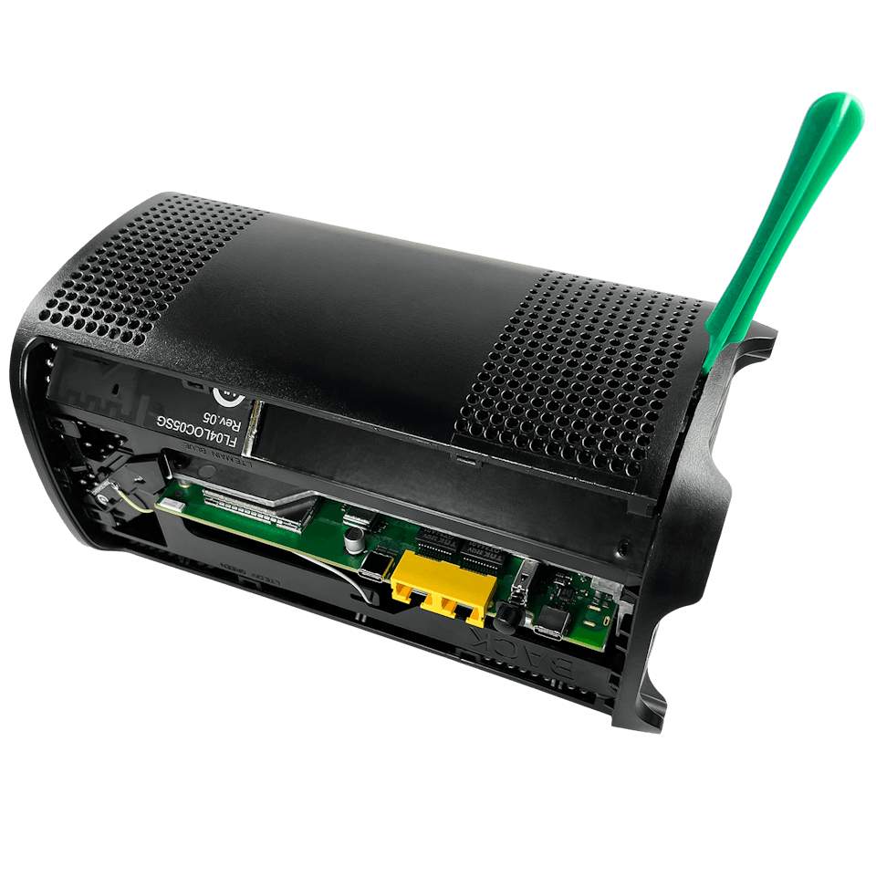
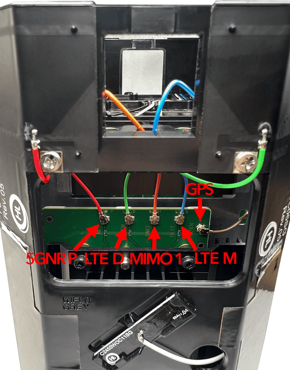
Step 8: Rotate the gateway to see a series of five cables connected to the board by small U.Fl connectors.
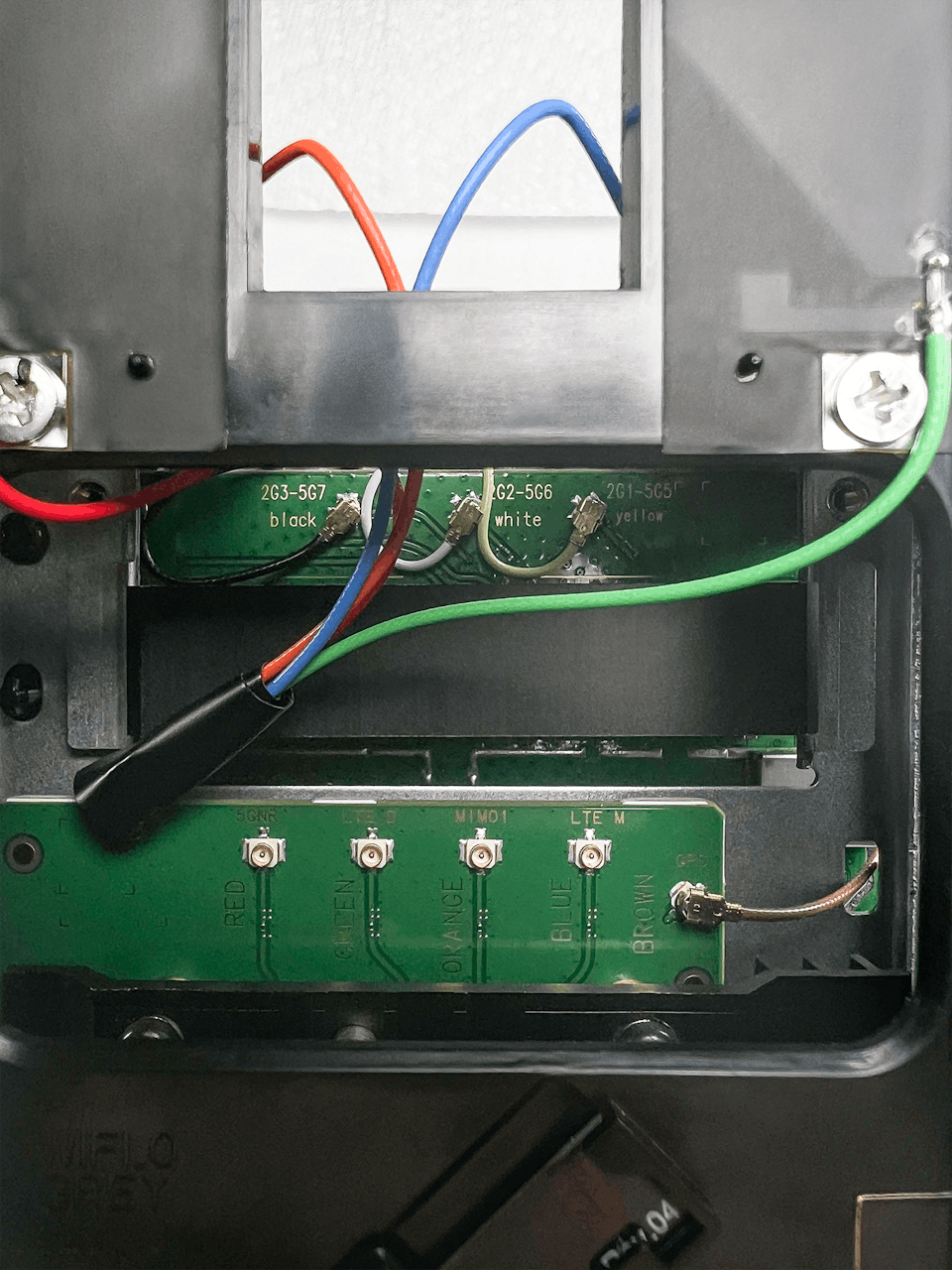
- The red, green, orange, and blue cables located on the U.FL ports labeled “5GNR P”, “LTE D”, “MIMO 1”, and “LTE M”, respectively, are used for cellular antennas. These cables will need to be disconnected.
- The brown cable located on the U.FL port labeled “GPS” is used by device’s the GPS antenna. This cable will remain in place.
Step 9: Use a prying tool or pair of tweezers to very carefully disconnect the red, green, orange, and blue cables.
NOTE: Be very careful. U.Fl connectors can be quite fragile. Make sure you’re very gentle to avoid breaking the connector when disconnecting it from the board.
NOTE: These pairings are preliminary and based on the names of the ports (5GNR P, LTE D, MIMO1, and LTE M). Due to this, we highly recommend that users test other port-pairings to see if other configurations can provide even better results.
Step 10: Once the U.Fl cables for the internal antennas are fully disconnected, tape them together and move them to the side of the inside the inner enclosure and out of the way.
Step 11: Route each pigtail adapter through its corresponding vent port on the bottom of the device, as shown below:
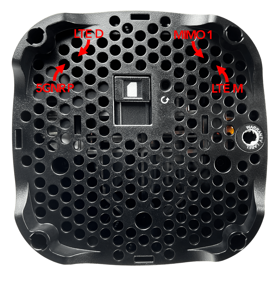
NOTE: Routing the pigtails through the vent ports shown above helps prevent the pigtail adapters from laying against the internal heatsink. This heatsink can get hot during normal gateway operations and could potential damage the cables if they are laid directly against it.
Step 12: Install your U.FL to SMA-Female pigtail adapters by very carefully aligning and pressing them down into the ports you opened up in Step 9. A quiet “click” can often be heard once the connectors are pressed down and fully connected.

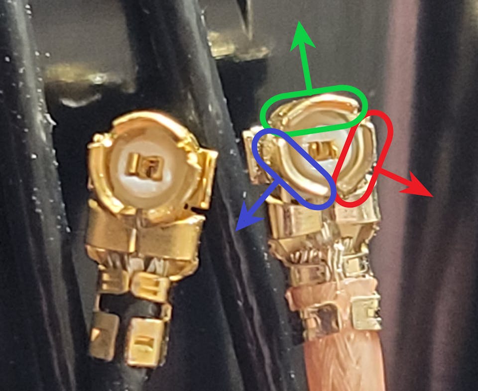
Tip: If you are struggling to get the pigtail connected, we recommend using a tweezers to spread the petals of the U.FL connector further apart, as shown in the image below:
Step 13 (Optional): For each pigtail adapter, loop a piece of tape around it’s cable and label the name of the port (5GNP P, LTE D, MIMO 1, LTE M) it connects to.
Step 14: Reassemble everything in reverse order. Make sure that your power button is in the off position before reconnecting the battery.
Congrats! Your T-Mobile 5G Internet Gateway should now be ready to connect it’s newly installed external antenna adapter cables to your external antenna(s)!
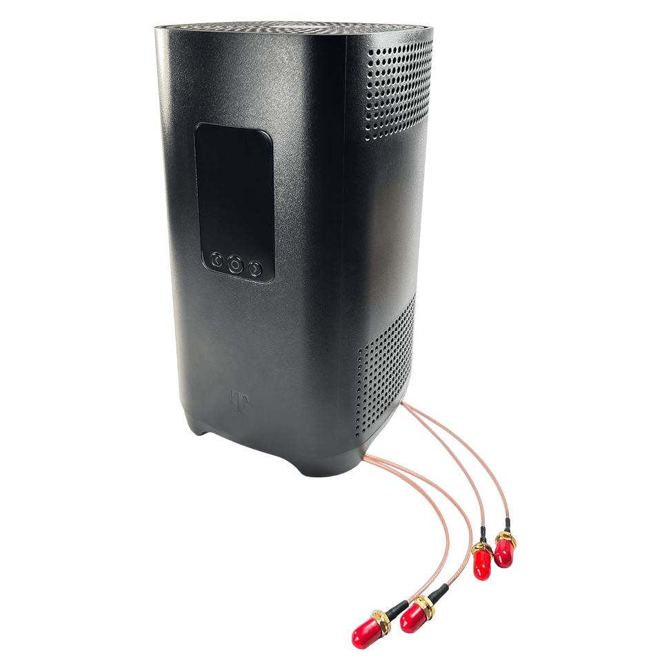
Step 15: Connect your external MIMO Antenna(s) to the labeled adapters installed in your Gateway in the order shown below:

Congrats! Your T-Mobile 5G Internet Gateway is now connected to your more powerful MIMO External Antennas.
Positioning and Aiming MIMO Antennas
Positioning and aiming MIMO antennas well is crucial to getting the best performance to your T-Mobile 5G Internet Gateway, or indeed any other hotspot.
We’ve actually compiled a detailed UHURA instruction manual to accompany our own MIMO Antenna Kits, where we go into depth on the best ways to aim the antennas.
The goal is to find the best location and direction for the antenna(s), to maximize data rates to the T-Mobile Gateway. It can take a little patience, but can have a huge impact – it’s worth a bit of extra effort!
Connect your MIMO external antennas to your modified T-Mobile 5G Internet Gateway via the newly installed pigtail adapters, and go outside with your “test-rig”.
With each location and direction you try, run a couple speed tests, and make a note of the results. Here are all the locations and directions where we recommend testing your MIMO antenna:
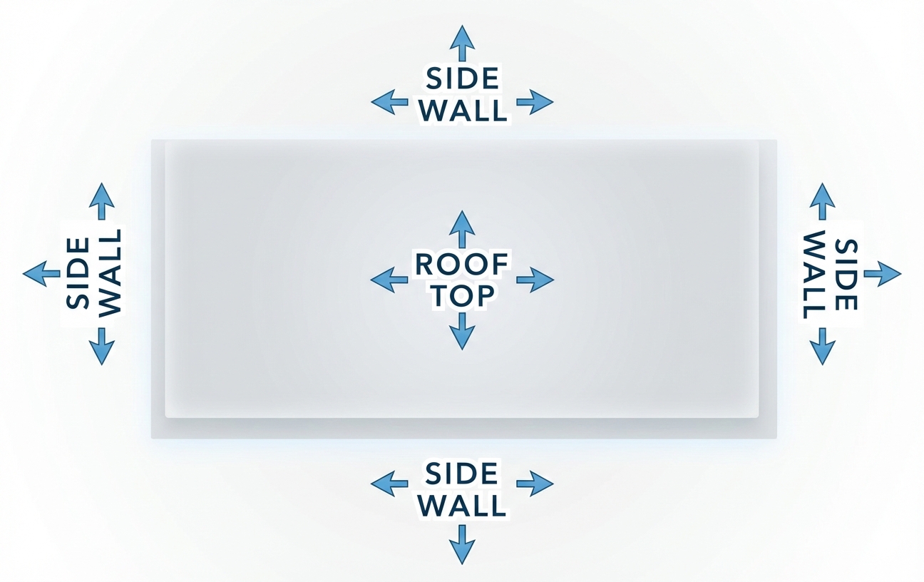
Pro tip: Don’t just go to the highest point of the roof! While signal is generally stronger the higher you go, there’s also often more interference. We’ve found it’s often better to mount the antenna(s) on the side of the building where the structure can shield the antennas from interference.
Once you’ve found the position which gets you the highest data rates to the T-Mobile Gateway, that’s where you’ll want to install the MIMO antenna. Go ahead and mount the antenna, run cables inside, connect everything up, and enjoy superior data rates!
T-Mobile 5G Internet Gateway Technical Specifications
-
5G Bands: n24, n41, n66, n71, n77
-
4G LTE Bands: B2, B4, B5, B12, B26, B41, B46, B66, B71
-
Model: Qualcomm Snapdragon X62
-
Networking: 5G NR (SA/NSA), 4G LTE
- MIMO Support: 4×4 with internal antennas or external antennas
- LTE-A Carrier Aggregation: Yes
- Technologies: Wi-Fi 6 – 802.11ax
- Bands: Simultaneous 2.4 GHz and 5 GHz
- Cellular Antenna Ports: 4x internal U.FL connectors
-
Ethernet Ports: 2x Gigabit LAN ports
- SIM Slot: 1x SIM (4FF)
- Other Ports: 1x USB-C (Power), 1x USB-C (Data/Test Port)
Other Helpful Resources
T-Mobile Gateway (Sagemcom Fast 5688W) Documentation
A Helpful Guide on Installing and Maintaining U.FL Connectors